Fitting an Automatic Shrink Wrapping Line Into Your Floor Plan
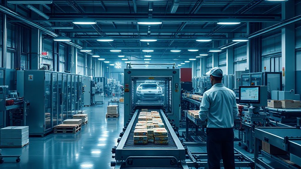
The factory floor is already busy: pallets stacked near the loading bay, a conveyor turning toward dispatch, and operators moving between stations. Now a new Shrink wrapping machine has to go in without blocking any of it. The real question is not which model to buy, but where the line can live so that product flows in one direction, waste moves out quickly, and people can still work safely around it.
Space planning for packaging equipment is a sequence problem disguised as a floor area problem. A machine that fits on paper can still fail in practice if its infeed faces the wrong aisle or its tunnel exit dumps packs into a walkway. The sections below walk through the footprint decisions that matter before the machine lands.
Start With the Flow, Not the Machine Dimensions
Most layout mistakes begin with a tape measure. Teams measure the available floor space, compare it to the machine’s length and width, and declare the job done. What they miss is the direction product travels before and after wrapping, and how that path interacts with everything else on the floor.
Walk the existing route from the last production step to dispatch. Mark where product currently pauses, where it gets stacked, and where it waits for transport. The wrapping line should sit on that route rather than beside it, because every right-angle turn adds handling time and floor congestion.
Map the three zones around the machine
- Infeed accumulation: a short buffer where products queue before entering the wrapper, sized to absorb brief stoppages upstream.
- Wrapping and tunnel zone: the machine body plus clearance for maintenance access on the service side.
- Outfeed and takeaway: space for wrapped packs to cool, be inspected, and move to palletizing or dispatch without backing up.
These three zones, not the machine alone, define the true footprint. A common error is allocating space only for the wrapper and tunnel, then discovering there is nowhere for finished packs to sit while the film sets.
Footprint Considerations for an Automatic Shrink Wrapping Machine
An Automatic Shrink Wrapping machine typically combines a sealing section, a shrink tunnel, and a conveyor connecting them. Each part has its own space demand, and the tunnel is usually the longest single element. Planning around the tunnel first often reveals whether the line should run straight, L-shaped, or in a compact U.
Service access is the most frequently underestimated requirement. Operators need room to load film rolls, clear jams, clean the tunnel, and reach electrical panels. If the service side faces a wall or a fixed rack, every minor intervention becomes a production stop.
Clearance and aisle logic
Leave walking space on the operator side and a wider gap on the maintenance side. Keep the tunnel exit clear of forklift routes, because wrapped packs emerging into traffic create both damage and safety risk. Where floor space is tight, consider elevating the outfeed conveyor so packs travel over an aisle rather than across it.
Utilities and floor condition
Check power supply location, compressed air points if required, and floor levelness before finalizing position. A machine placed far from its power source needs longer cabling, which can become a trip hazard or a code issue. Also confirm that the floor can carry the machine’s weight plus the dynamic load of product moving through it.
Matching the Line Configuration to Available Space
Not every factory can accommodate a long straight line. Machine configuration should follow the room’s shape, not the other way around. A straight-through layout suits long, narrow bays, while an L-shaped or angled arrangement can fit a wrapping line into a corner that would otherwise be dead space.
The shrink tunnel Machine is the element that most often forces a layout decision, because its length and heat output affect both placement and ventilation. Positioning the tunnel near an outer wall or ventilation point helps manage heat, but only if the product path still flows logically.
| Layout option | Best suited to | Main trade-off |
|---|---|---|
| Straight-through | Long bays with clear aisles | Consumes the most linear floor length |
| L-shaped | Corner spaces or compact rooms | Needs a transfer point that can slow flow |
| U-shaped | Operators supervising both ends | Requires careful separation of infeed and outfeed traffic |
Choose the configuration that keeps the operator within sight of both the infeed and the tunnel exit. That single principle prevents many daily delays, because jams and film breaks get noticed before packs pile up.
Commissioning Without Disrupting the Existing Line
Installation day is where good planning pays off. Sequence the work so the new line is assembled in a staging area and moved into position during a planned production gap. Running cables, positioning conveyors, and testing the tunnel can happen before the machine is tied into the live flow.
Plan a trial period where the wrapping line runs alongside existing packing methods. This lets operators learn the machine’s rhythm and exposes layout problems while there is still flexibility to shift a conveyor or widen an aisle. Keep a marked walkway around the installation at all times, and confirm that emergency stops remain reachable from both sides.
Finally, document the final layout with dimensions, utility points, and clearance zones. A floor plan that lives only in memory tends to erode as pallets and racks creep into service areas. The wrapping line works best when its space is treated as reserved, not as overflow storage.